The Request:
I was approached by a client who wanted me to build their multi tenant network for a small office building. During the initial meeting it came out that they already had equipment and would like to use this equipment without purchasing much more. This is what I had to work with:
- 1 x Cisco X8XX Series ISR1
- 6 x Cisco 2960X Switches
The client also has an existing Cisco Unified Communications System that they will be configuring to provide voice services to all of the tenants. There will be no LAN-to-LAN communications between the tenants. There will be a reasonable amount of commercial grade Internet access and the tenants will be allowed to host some services locally (e-mail, collaboration software, etc.).
My Proposed Solution:
Since the switches are strictly layer two devices and there will be zero tenant-to-tenant communications at the LAN level I proposed a VRF2 solution utilizing the ISR as a router-on-a-stick. There will be a VRF for each tenant, a VRF for the voice service, a VRF for the WAN/Internet circuit. This will allow for strict separation of tenants while still allowing the sharing of voice and Internet services. Each VRF will reside in a VLAN that will be trounced to the stack of switches via a port-channel. I will leave the management VLAN in the global routing table.
The Proof of Concept:
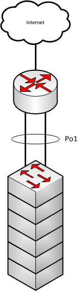
Diagrams:
Here is a small, basic, diagram of what we will be building:
Here is how we broke down the VLANs/VRFs for the PoC3 lab:
VRF/VLAN Breakdown:
| VRF Name | Route Distinguisher | VLAN ID | IP Address | Description |
|---|---|---|---|---|
| WAN | 99 | N/A | 10.20.30.253/24 |
Internet Access |
| red | 1 | 1 | 192.168.1.1/24 |
Tenant 1 |
| blue | 2 | 2 | 192.168.2.1/24 |
Tenant 2 |
| green | 3 | 3 | 192.168.1.1/24 |
Tenant 3 - Dup Red IP |
| voice | 111 | 111 | 10.1.1.1/24 |
Shared Voice |
| N/A | N/A | 999 | 10.9.9.1/24 |
Management |
Remember: VRFs are case sensitive!
Switch Configuration Overview:
We will begin with the switches since they are the most basic. The switches will be stacked and the VLANs will be configured for each tenant, voice, and management. Since the switches are strictly layer 2 they will not be concerned with any of the VRF specific information.
Router Configuration Overview:
The router is where the real work takes place. The router we are using in the lab is a Cisco 2821 running IOS 15.1.4M7 Advanced Enterprise Services.
VRF Configuration
The first thing we did was configure the VRFs individually:
ip vrf WAN
 rd 65000:99
!
ip vrf red
 rd 65000:1
!
ip vrf blue
 rd 65000:2
!
ip vrf green
 rd 65000:3
!
ip vrf voice
 rd 65000:111
I like to match the RD 4 to the BGP ASN 5 and VLAN number whenever possible. As we begin importing an exporting routing to/from MP-BGP6 it will definitely help you keep things straight! In this scenario we are using an private ASN since we are not performing any external peering.
MP-BGP Configuration
Now that we have our VRFs setup I like to go ahead and configure MP-BGP. This can also be done after you configure all of your VLANs. MP-BGP is used in the scenario only for leaking routes between VRFs. Since each VRF is its own virtual router you have to have a mechanism to allow them to share, or “leak”, routes between virtual routers. MP-BGP is that mechanism and is MUCH easier than it sounds! See configuration below:
router bgp 65000
 bgp log-neighbor-changes
 !
 address-family ipv4 vrf WAN
  redistribute connected
 exit-address-family
!
 address-family ipv4 vrf red
  redistribute connected
 exit-address-family
 !
 address-family ipv4 vrf blue
  redistribute connected
 exit-address-family
 !
 address-family ipv4 vrf green
  redistribute connected
 exit-address-family
!
 address-family ipv4 vrf voice
  redistribute connected
 exit-address-family
Now that we have MP-BGP configured we will set the export and import statements within the VRFs. When thinking of import and export statements I always like to imagine I am standing on top of the VRF looking at MP-BGP. When I export from my VRF I am sending it to MP-BGP and when I import into my VRF I am importing from MP-BGP. Below is the configuration from the lab:
ip vrf WAN
 rd 65000:99
 route-target export 65000:99
 route-target import 65000:1
 route-target import 65000:2
 route-target import 65000:3
!
ip vrf blue
 rd 65000:1
 route-target export 65000:1
 route-target import 65000:99
 route-target import 65000:111
!
ip vrf red
 rd 65000:2
 route-target export 65000:2
 route-target import 65000:99
 route-target import 65000:111
!
ip vrf green
 rd 65000:3
 route-target export 65000:3
 route-target import 65000:99
 route-target import 65000:111
!
ip vrf voice
 rd 65000:111
 route-target export 65000:111
 route-target import 65000:1
 route-target import 65000:2
 route-target import 65000:3
Lets take a look at the WAN VRF import/export statements more closely:
ip vrf WAN
 rd 65000:99
 route-target export 65000:99
 route-target import 65000:1
 route-target import 65000:2
 route-target import 65000:3
In this statement you will see that I am exporting 65000:99 to MP-BGP and am importing 65000:1, 65000:2, and 65000:3 from MP-BGP. Those imports are the routes for VRF red, blue, and green respectively. You will also see that under each of those VRFs they are importing 65000:99. That gives them access to the routes in the WAN VRF. You will also notice that we are not importing the voice VRF (65000:111) into the WAN VRF nor are we importing the WAN VRF routes into the voice VRF. This will isolate the voice network from the Internet while still allowing the vice VLAN to be accessed by the tenants.
Port-Channel Configuartion:
Next we will configure the port-channel from the Cisco 2800 to the switch stack. Since we are using a 2821 in the lab we only have access to two ethernet ports. We are using G0/0 for WAN connectivity and we will use G0/1 as one half of the port-channel. This will work fine for a PoC. Below you will find the configuration from the lab:
interface GigabitEthernet0/1
 no ip address
 duplex auto
 speed auto
 no keepalive
 channel-group 1
!
interface Port-channel1
 no ip address
!
interface Port-channel1.1
 encapsulation dot1Q 1 native
 ip vrf forwarding red
 ip address 192.168.1.1 255.255.255.0
 ip nat inside
 ip virtual-reassembly in
!
interface Port-channel1.2
 encapsulation dot1Q 2
 ip vrf forwarding blue
 ip address 192.168.2.1 255.255.255.0
 ip nat inside
 ip virtual-reassembly in
!
interface Port-channel1.3
 encapsulation dot1Q 3
 ip vrf forwarding green
 ip address 192.168.1.1 255.255.255.0
 ip nat inside
 ip virtual-reassembly in
!
interface Port-channel1.111
 encapsulation dot1Q 111
 ip vrf forwarding voice
 ip address 10.1.1.1 255.255.255.0
 ip nat inside
 ip virtual-reassembly in
!
interface Port-channel1.999
 encapsulation dot1Q 999
 ip address 10.9.9.1 255.255.255.0
 ip virtual-reassembly in
Remember: Configure the VRF information under the interface FIRST! It will erase all layer 3 information on the interface when configured. This is a very basic setup. First interface G0/1 is added to channel-group 1. Then interface port-channel 1 on configured with no IP address. This is because we are utilizing this router as a router-on-a-stick. That means we must configure the VLANs as sub interfaces of the port-channel. Each of these sub interfaces will be assigned to their respective VRF and dot1q VLAN. These are also configured as “ip nat inside” interfaces as they will be NAT’d through the WAN VRF.
WAN Interface Configuration:
interface GigabitEthernet0/0
 description INTERNET INTERFACE - DO NOT TOUCH!!!
 ip vrf forwarding WAN
 ip address 10.20.30.253 255.255.255.0
 ip nat outside
 ip virtual-reassembly in
 duplex auto
 speed auto
The WAN interface configuration is quite straight forward. First we place interface G0/0 into the WAN VRF and then add the IP information.
Default Route and NAT Configuration
Now that all of the interface, VLANs, VRFs, and MP-BGP are configured we are ready to give these tenants access to the Internet. Below is the configuration from the lab:
ip route vrf WAN 0.0.0.0 0.0.0.0 10.20.30.1
ip route vrf blue 0.0.0.0 0.0.0.0 10.20.30.1
ip route vrf green 0.0.0.0 0.0.0.0 10.20.30.1
ip route vrf red 0.0.0.0 0.0.0.0 10.20.30.1
!
ip access-list extended BLUENAT
 permit ip 192.168.2.0 0.0.0.255 any
ip access-list extended GREENNAT
 permit ip 192.168.1.0 0.0.0.255 any
ip access-list extended REDNAT
 permit ip 192.168.1.0 0.0.0.255 any
ip access-list extended WAN
 permit ip any any log
!
ip nat inside source list BLUENAT interface GigabitEthernet0/0 vrf blue overload
ip nat inside source list GREENNAT interface GigabitEthernet0/0 vrf green overload
ip nat inside source list REDNAT interface GigabitEthernet0/0 vrf red overload
First you will see the default routes for each VRF. This is a straightforward configuration that tells each VLAN how to leave the network. The voice VLAN is not given a default route as it is not allowed access outside and does not know about the WAN VRF. Next we configured extended access lists for each VRF and called out the IP address space. Afterward we configured the NAT overload statements for each VRF. This configuration is pretty standard if you are familiar with traditional NAT configuration.
Static NAT for Outside Access
We also had to configure static NAT to allow people on the Internet the ability to access services internal to each tenant. Below is the configuration from the lab:
ip nat inside source static tcp 192.168.1.1 443 10.20.30.253 80 vrf green extendable
ip nat inside source static tcp 192.168.1.1 443 10.20.30.253 443 vrf red extendable
We used these static NAT statements to show that the system is capable of NAT’ing to the same IP in different VRFs. As you will see in the output below this works without issue:
2821#sh ip nat translations  verbose
Pro Inside global      Inside local       Outside local      Outside global
tcp 10.20.30.253:80    192.168.1.1:443    10.20.30.102:62834 10.20.30.102:62834
    create 00:00:34, use 00:00:33 timeout:86400000, left 00:00:26,
    flags:
extended, timing-out, use_count: 0, VRF : green, entry-id: 10, lc_entries: 0
tcp 10.20.30.253:80    192.168.1.1:443    10.20.30.102:62835 10.20.30.102:62835
    create 00:00:33, use 00:00:32 timeout:86400000, left 00:00:27,
    flags:
extended, timing-out, use_count: 0, VRF : green, entry-id: 11, lc_entries: 0
tcp 10.20.30.253:80    192.168.1.1:443    ---                ---
    create 00:00:42, use 00:00:33 timeout:0,
    flags:
static, extended, extendable, use_count: 2, VRF : green, entry-id: 7, lc_entries: 0
tcp 10.20.30.253:443   192.168.1.1:443    10.20.30.102:62826 10.20.30.102:62826
    create 00:00:38, use 00:00:37 timeout:86400000, left 00:00:22,
    flags:
extended, timing-out, use_count: 0, VRF : red, entry-id: 8, lc_entries: 0
tcp 10.20.30.253:443   192.168.1.1:443    10.20.30.102:62827 10.20.30.102:62827
    create 00:00:38, use 00:00:37 timeout:86400000, left 00:00:22,
    flags:
extended, timing-out, use_count: 0, VRF : red, entry-id: 9, lc_entries: 0
tcp 10.20.30.253:443   192.168.1.1:443    ---                ---
    create 00:02:42, use 00:00:38 timeout:0,
Pro Inside global      Inside local       Outside local      Outside global
    flags:
static, extended, extendable, use_count: 2, VRF : red, entry-id: 4, lc_entries: 0
One issue I did run into, and I am still investing, is that remote access to the WAN interface though both SSH and Telnet stopped working once we configured the static NAT statements. We removed the statements and instantly things began working again. To work around this we configured a loopback interface and NAT’d port 22. This allowed external access once again. Below is the configuration form the lab:
interface Loopback0
 ip vrf forwarding WAN
 ip address 10.255.255.255 255.255.255.255
!
ip nat inside source static tcp 10.255.255.255 22 10.20.30.253 22 vrf WAN extendable
We placed the loopback in the WAN VRF to isolate it as a WAN service.
Conclusion
Although I ran into a few roadblocks along the way I was able to get all of the services the client requested working on the equipment they provided. IF anyone sees any issue with the above configurations or would like more information feel free to comment below.
THANKS!
First I would like to that Greg Ferro whose book Arse First Method of Technical Blogging really got me motivated to start writing. I had been keeping lists of ideas for quite some time but his book really helped me put a plan together to get started! I would also like to thank Paul Stewart for his great blog at PacketU, Marko Milivojevic for his great VRF Route Leaking explanation at IPExpert and Jeremy Stretch for his excellent VRF blogs over at PacketLife.
7 comments
Paul Stewart, CCIE 26009 (Security)
Wednesday, Dec 18, 2013
Jon
Tuesday, Oct 14, 2014
mo1640
Saturday, May 23, 2015
Great blog. I just wanted to point out that red and blue are swapped in the first section.
IP is also incorrect here:
Dan
In reply to mo1640
Thursday, Jun 11, 2015
Root
Wednesday, Jan 11, 2017
Test
Monday, Sep 2, 2019
Dan
In reply to Test
Saturday, May 2, 2020
Say something
Thank you
Your post has been submitted and will be published once it has been approved.
OK